86 Lockout Relay Wiring Diagram : Intro To Relays 2 Ansi Ieee Relay Numbers / Wiring connections position function description terminal strip j5 1 electric lock relay relay common 2 electric lock relay n.o.. This relay is not self resettable, it requires manual resetting for normalizing the protection circuit. Static relay with terminals for external auxiliary voltage supply u. Hvac lockout relay wiring diagram lockout relay abb 86 relay peugeot 806 and expert engine type dhx xud9btf bosch as3 b2200 ac relay mazda forum mazda enthusiast forums camry fan switch wiring diagram toyota cooling fan wiring diagram car ac pressure switch wiring diagram home ac compressor wiring diagram wiring diagram. Insulation colors help to trace circuits and to make proper connections. Power door locks wiring diagram 1999 dodge 5 wire door lock wiring wiring diagram meta 2005 mercury grand marquis door lock wiring diagram wiring
Next, i ran power from the battery to the #30 terminal of the relay and then out the #87 terminal to the line lock. Note that the pin configuration is different on a standard iso relay than on the lucas What makes power lock and power window circuits confusing is there are actually four sets of switch contacts inside each switch. Hvac lockout relay wiring diagram lockout relay abb 86 relay peugeot 806 and expert engine type dhx xud9btf bosch as3 b2200 ac relay mazda forum mazda enthusiast forums camry fan switch wiring diagram toyota cooling fan wiring diagram car ac pressure switch wiring diagram home ac compressor wiring diagram wiring diagram. Relays are designed so that a small current circuit will be able to control a large current circuit.
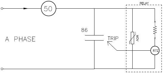
Anti Pumping And Lockout Relays from electrical-engineering-portal.com The 87 posts for both go to the corresponding solenoid. Static relay with terminals for external auxiliary voltage supply u. Relays are designed so that a small current circuit will be able to control a large current circuit. Next, i ran power from the battery to the #30 terminal of the relay and then out the #87 terminal to the line lock. As the name suggests, this relay once operated locks out the circuit. Substitute with a change over relay (part no rel7db available from us) and wire it in as per the relay schematic shown in fig 1. The bracket that mounts the solenoid in the door provides the. 87 and 87a are the two contacts to which 30 will connect.
86 87a 30 factory lock relay system this wiring diagram is for cars with factory lock relays.
Relay is triggered by activation inputs 10, 11, or 15. The purpose of an 86 relay is to serve as an intermediary element between one or more protective relays and one or more control devices, both expanding the number of control elements actuated by any one. 87 and 87a are the two contacts to which 30 will connect. This relay is not self resettable, it requires manual resetting for normalizing the protection circuit. The bracket that mounts the solenoid in the door provides the. Page 3 wiring harness and wires every wire is a specific size with colored or striped insulation that is indicated on the wiring diagrams. Shallco series 26 lockout relay lor 86 relay master trip has a continuous rating of 30a 600 vac 2 position stops factory set for trip and reset 1 to 10 sections standard for other options contact factory up to 20 sets of no. 86 84 82 80 78 88 86 84 82 80 90 88 86 84 82 92 90 88 86 84 94 92 90 88 86 Wiring connections position function description terminal strip j5 1 electric lock relay relay common 2 electric lock relay n.o. Relay pack has wiring to each door that simply plugs into the actuator assembly. Note that the pin configuration is different on a standard iso relay than on the lucas I tapped the power at the parking brake switch and sent it to the line lock button and then from the line lock button to the #86 terminal of the relay. 85 and 86 are the coil pins while 30, 87, and 87a are the contact pins.
If the coil is not activated, 30 will always be connected to 87a. Blue harness coming into vehicle from driver's Next, i ran power from the battery to the #30 terminal of the relay and then out the #87 terminal to the line lock. Relay pack has wiring to each door that simply plugs into the actuator assembly. Shallco series 26 lockout relay lor 86 relay master trip has a continuous rating of 30a 600 vac 2 position stops factory set for trip and reset 1 to 10 sections standard for other options contact factory up to 20 sets of no.
Bus Differential Fault Waveform Analysis Voltage Disturbance from voltage-disturbance.com I am not clear whether the entry point of the three wires (yellow/green/purple) going to the pcm represent the three large connectors to the pcm (crank volt, crank signal. Looking at the diagram, we see the pinout of a typical 12v relay. As the name suggests, this relay once operated locks out the circuit. Blue harness coming into vehicle from driver's I tapped the power at the parking brake switch and sent it to the line lock button and then from the line lock button to the #86 terminal of the relay. The purpose of an 86 relay is to serve as an intermediary element between one or more protective relays and one or more control devices, both expanding the number of control elements actuated by any one. The 87 posts for both go to the corresponding solenoid. Relay pack has wiring to each door that simply plugs into the actuator assembly.
Electrical lockout (see device function 86) on abnormal conditions.] 6 starting circuit breaker is a device
Note that each pin is numbered. 86 85 87a omiting mast delay for those who don't want the 10 sec delay for the mast to retract or who have a faulty delay module: Shallco series 26 lockout relay lor 86 relay master trip has a continuous rating of 30a 600 vac 2 position stops factory set for trip and reset 1 to 10 sections standard for other options contact factory up to 20 sets of no. The 87 posts for both go to the corresponding solenoid. I am not clear whether the entry point of the three wires (yellow/green/purple) going to the pcm represent the three large connectors to the pcm (crank volt, crank signal. The purpose of an 86 relay is to serve as an intermediary element between one or more protective relays and one or more control devices, both expanding the number of control elements actuated by any one. Next, i ran power from the battery to the #30 terminal of the relay and then out the #87 terminal to the line lock. Hvac lockout relay wiring diagram lockout relay abb 86 relay peugeot 806 and expert engine type dhx xud9btf bosch as3 b2200 ac relay mazda forum mazda enthusiast forums camry fan switch wiring diagram toyota cooling fan wiring diagram car ac pressure switch wiring diagram home ac compressor wiring diagram wiring diagram. Relays are designed so that a small current circuit will be able to control a large current circuit. Connection diagrams, in instruction books, and in specifications. Lock out relay is an electromechanical relay which latches its output contact. Blue harness coming into vehicle from driver's When start relay and start capacitor are installed, start thermistor is not used.
Note that each pin is numbered. The 87 posts for both go to the corresponding solenoid. Power door locks wiring diagram 1999 dodge 5 wire door lock wiring wiring diagram meta 2005 mercury grand marquis door lock wiring diagram wiring I found that the radio shack 9vdc mini relay was a drop in replacement! It is also known as master trip relay and its ansi code is 86.
Introduction To Breaker Failure Schemes 50bf Valence Electrical Training Services from relaytraining.com 86 85 87a omiting mast delay for those who don't want the 10 sec delay for the mast to retract or who have a faulty delay module: Positive trip from switch from alarm door driver output to door locks, power (12v positive) and ground 87 86 12v positive 87a 30 85 87 87a 85 factory lock relay system this wiring diagram is for cars with factory lock relays. Power door locks wiring diagram 1999 dodge 5 wire door lock wiring wiring diagram meta 2005 mercury grand marquis door lock wiring diagram wiring 85 and 86 are the coil pins while 30, 87, and 87a are the contact pins. Lock out relay is an electromechanical relay which latches its output contact. Hvac lockout relay wiring diagram lockout relay abb 86 relay peugeot 806 and expert engine type dhx xud9btf bosch as3 b2200 ac relay mazda forum mazda enthusiast forums camry fan switch wiring diagram toyota cooling fan wiring diagram car ac pressure switch wiring diagram home ac compressor wiring diagram wiring diagram. Static relay with terminals for external auxiliary voltage supply u. I am not clear whether the entry point of the three wires (yellow/green/purple) going to the pcm represent the three large connectors to the pcm (crank volt, crank signal.
I am not clear whether the entry point of the three wires (yellow/green/purple) going to the pcm represent the three large connectors to the pcm (crank volt, crank signal.
86 84 82 80 78 88 86 84 82 80 90 88 86 84 82 92 90 88 86 84 94 92 90 88 86 Blue harness coming into vehicle from driver's It is then grounded through terminal #85 on the relay. 86 85 87a omiting mast delay for those who don't want the 10 sec delay for the mast to retract or who have a faulty delay module: Electrical lockout (see device function 86) on abnormal conditions.] 6 starting circuit breaker is a device Looking at the diagram, we see the pinout of a typical 12v relay. When start relay and start capacitor are installed, start thermistor is not used. Lock out relay is an electromechanical relay which latches its output contact. Relay pack has wiring to each door that simply plugs into the actuator assembly. 85 and 86 are the coil pins while 30, 87, and 87a are the contact pins. Power door locks wiring diagram 1999 dodge 5 wire door lock wiring wiring diagram meta 2005 mercury grand marquis door lock wiring diagram wiring Relay is triggered by activation inputs 10, 11, or 15. As the name suggests, this relay once operated locks out the circuit.