Four Pin Trailer Wiring Diagram / 7 Way Diagram Aj S Truck Trailer Center / The ground wire should be run from the frame of the.. Your owners manual should have another diagram to help you. It will help immediately in fixing errors. It consists of guidelines and diagrams for various kinds of wiring strategies and other things like lights, windows, and so on. Use on a small motorcycle trailer, snowmobile trailer or utility trailer. Variety of 5 wire to 4 wire trailer wiring diagram.
The circuits are for left and right brake lights and running lights. First, knowing the diagram of cables for trailer will be useful during troubleshooting. Many trailers have three circuits. For instance , in case a module is usually powered up and it sends out a new signal of half the voltage and the technician would not know this, he would think he provides a challenge, as this individual would expect a 12v signal. Three wires are for the trailer while the last wire is the ground wire.
Wiring Trailer Lights With A 4 Way Plug It S Easier Than You Think Etrailer Com from www.etrailer.com Three wires are for the trailer while the last wire is the ground wire. Wiring diagram consists of several comprehensive illustrations that present the connection of varied things. They also provide a wire for a ground connection. 4 pin trailer light wiring diagram : Search for trailer wiring diagrams 4 pin here and subscribe to this site trailer wiring diagrams 4 pin read more! For instance , in case a module is usually powered up and it sends out a new signal of half the voltage and the technician would not know this, he would think he provides a challenge, as this individual would expect a 12v signal. Anyone, including you, can do it in a short period of time. Variety of 5 wire to 4 wire trailer wiring diagram.
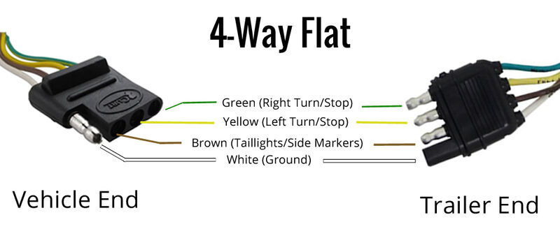
The four wires control the turn signals, brake lights and taillights or running lights.
It will help immediately in fixing errors. The 5th pin, a blue wire, gives power to operate (or disable) the trailer brakes. A wiring diagram is a streamlined standard photographic representation of an electric circuit. Three wires are for the trailer while the last wire is the ground wire. While none of these are things we look forward to when pulling a trailer, they are also easy to correct. 4 pin trailer wiring diagramtrailer plug adapter4 pin trailer connector color code 4 wire trailer plugtrailer light wiringtrailer wiring diagram7 pin to 4 pi. These four colored wires make up your trailer's wiring system. Trailer wiring diagrams trailer wiring connectors various connectors are available from four to seven pins that allow for the transfer of power for the lighting as well as auxiliary functions such as an electric trailer brake controller, backup lights, or a 12v power supply for a winch or interior trailer lights. As the name implies they use four wires to carry out the vital lighting functions. This is a short video series of the steps that i have taken to refurbish and old utility trailer that was designed and built by my father. Many trailers have three circuits. 4 pin to 7 pin trailer adapter wiring diagram. It consists of guidelines and diagrams for various kinds of wiring strategies and other things like lights, windows, and so on.
Use on a small motorcycle trailer, snowmobile trailer or utility trailer. A wiring diagram is a streamlined standard photographic representation of an electric circuit. It shows the components of the circuit as simplified shapes, and the gift and signal links between the devices. 4 pin trailer wiring diagram this type of connector is normally found on utvs, atvs and trailers that do not have their own braking system. Trailer wiring diagrams trailer wiring connectors various connectors are available from four to seven pins that allow for the transfer of power for the lighting as well as auxiliary functions such as an electric trailer brake controller, backup lights, or a 12v power supply for a winch or interior trailer lights.
Trailer Wiring Diagram Lights Brakes Routing Wires Connectors from mechanicalelements.com The 5th pin, a blue wire, gives power to operate (or disable) the trailer brakes. Use on a small motorcycle trailer, snowmobile trailer or utility trailer. 4 pin trailer light wiring diagram : The red and blue wire can be used for brake control or auxiliary. Find your trailer wiring diagrams 4 pin here for trailer wiring diagrams 4 pin and you can print out. Wiring diagram consists of several comprehensive illustrations that present the connection of varied things. Yellow and green are for left and right turns and braking. As a rule, you can find these connectors on the older trailers and older vehicles built in the u.s.
Most of us aren't electricians, but that doesn't mean wiring a trailer or replacing corroded wiring is beyond us.
Variety of 5 wire to 4 wire trailer wiring diagram. Variety of 7 pin to 4 pin trailer wiring diagram. 4 pin trailer wiring diagram this type of connector is normally found on utvs, atvs and trailers that do not have their own braking system. The four wires control the turn signals, brake lights and taillights or running lights. If a trailer has brakes, then it needs a connector with at least 5 pins. 4 pin to 7 pin trailer adapter wiring diagram. 3/4 inch by 1 inch 6 way rectangle connectors right turn signal (green), left turn signal (yellow), taillight (brown), ground (white). Trailer lighting/wiring kit for snowmobile trailer; The red and blue wire can be used for brake control or auxiliary. It includes instructions and diagrams for various types of wiring strategies along with other products like lights, home windows, and so on. Three wires are for the trailer while the last wire is the ground wire. Your owners manual should have another diagram to help you. Anyone, including you, can do it in a short period of time.
Trailer lighting/wiring kit for snowmobile trailer; Wiring your 4 pin to a 7 pin connector is not that difficult. Effectively read a wiring diagram, one provides to learn how the components within the method operate. Use on a small motorcycle trailer, snowmobile trailer or utility trailer. It shows the elements of the circuit as streamlined forms, and the power and signal links between the devices.
Trailer Wiring Diagram Trailers In Denver Co Denver Co Trailer Dealer For Enclosed And Flatbed Utiliity Trailers In Denver At All American Trailers from dealer-cdn.com 4 pin trailer wiring diagram this type of connector is normally found on utvs, atvs and trailers that do not have their own braking system. The red and blue wire can be used for brake control or auxiliary. It consists of guidelines and diagrams for various kinds of wiring strategies and other things like lights, windows, and so on. As a rule, you can find these connectors on the older trailers and older vehicles built in the u.s. The worst that usually happens with screwy trailer wiring is a blown fuse on the tow vehicle—or something wacky, like reversed turn signals or blinking brake lights. First, knowing the diagram of cables for trailer will be useful during troubleshooting. It symbolizes the electric powered circuits elements as simple styles, with all the genuine power and soil contacts between them as tinted circles. It will help immediately in fixing errors.
4 pin trailer wiring diagram this type of connector is normally found on utvs, atvs and trailers that do not have their own braking system.
Installing side marker clearance lights with two wires on trailer; It symbolizes the electric powered circuits elements as simple styles, with all the genuine power and soil contacts between them as tinted circles. When issues happen with the trailer, motorist might wish to know where the problem spot is located. Can also be used as custom wiring on trailers with 3 light/wire systems. A wiring diagram is a streamlined standard photographic representation of an electric circuit. Anyone, including you, can do it in a short period of time. It shows the components of the circuit as simplified shapes, and the gift and signal links between the devices. As a rule, you can find these connectors on the older trailers and older vehicles built in the u.s. These four colored wires make up your trailer's wiring system. Yellow and green are for left and right turns and braking. If a trailer has brakes, then it needs a connector with at least 5 pins. 4 wire trailer wiring diagram troubleshooting folks understand that trailer is a vehicle comprised of rather complicated mechanics. Use on a small motorcycle trailer, snowmobile trailer or utility trailer.