As part of your design process, you'll need to start with a block diagram, circuit schematic, and eventually a PCB layout
Home
› Sg3526 Inverter Circuit Diagram : 3 High Power Sg3525 Pure Sinewave Inverter Circuits Homemade Circuit Projects / In this second example, this pwm controller ic is used to generate a 220 volt ac supply from 12 volts dc.this circuit is based on sg3525a which is the same ic.
Sg3526 Inverter Circuit Diagram : 3 High Power Sg3525 Pure Sinewave Inverter Circuits Homemade Circuit Projects / In this second example, this pwm controller ic is used to generate a 220 volt ac supply from 12 volts dc.this circuit is based on sg3525a which is the same ic.
Sg3526 Inverter Circuit Diagram : 3 High Power Sg3525 Pure Sinewave Inverter Circuits Homemade Circuit Projects / In this second example, this pwm controller ic is used to generate a 220 volt ac supply from 12 volts dc.this circuit is based on sg3525a which is the same ic.. As 200 watts inverter circuit. By wallpaper april 07, 2021 figure 3 the schematic diagram of this projects. Hello sir swagatam,i have a 2200w rated refrigerator,a 2200w rated microwave oven ,4×65w fluorescent lights. 500w power inverter circuit using sg3526 irfp540 inverters dc converter electronics projects circuits. Pls sir i was asked to construct a pure sine wave inverter(not modified sine wave) using sg3525 and 555 ic or 4047 ic as my final year project to be passed on march 24th pls can u help me with a circuit diagram and also if you have any schematic of a pure sine wave (not modified)inverter not modified sine wave you can also send me the link but.
It use sg3526 and mosfet irfp540 so high efficiency than transistors,full protection Go to that page to read the explanation about above circuit design. In the electrical sector, a schematic diagram is usually used to describe the design or model of equipment. Circuit diagram of solar inverter using sg3525 is given below. Circuit diagram of solar inverter :
Sg3526 Inverter Circuit Diagram 500 W Inverter Circuit Diagram Cat 5 Wiring Diagram For Female Jack Viking Yenpancane Jeanjaures37 Fr Supply Voltage Collector Supply Voltage Logic Inputs Analog Inputs Output from i2.wp.com As 200 watts inverter circuit. We use q1, q2 is the mosfet acts as a power output. This schematic diagram come from circuit: mohammed ali on arduino inverter circuit; Figure 3 the schematic diagram of this projects. Hello sir swagatam,i have a 2200w rated refrigerator,a 2200w rated microwave oven ,4×65w fluorescent lights. It use sg3526 and mosfet irfp540 so high efficiency than transistors,full protection 500 watts mosfet power inverter circuit.
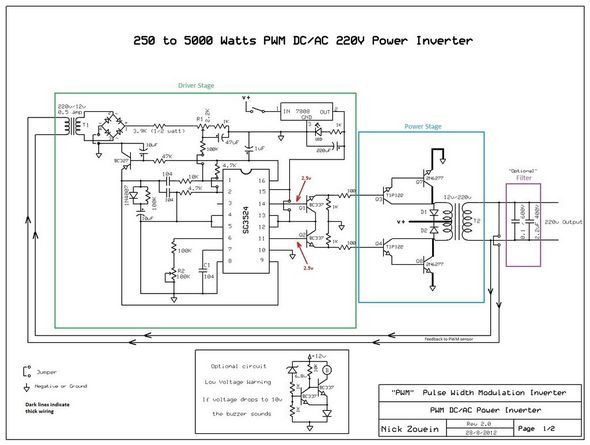
In the actual circuit, the switching element consists of two power fets, while the resistor to ground acts as a current sense (shunt) for the current limiter circuit inside the sg3526.
Your email address will not be published. mohammed ali on arduino inverter circuit; Power inverter circuit diagram pdf. Simple inverter block diagram in the block diagram below, starting from the frequency generator circuit or the oscillator. Dc/ac pure sine wave inverter jim doucet dan eggleston jeremy shaw mqp terms abc 20062007 advisor: As 200 watts inverter circuit. Circuit diagram of solar inverter using sg3525 is given below. I am presently constructing an inverter using your circuit diagram. 500w power inverter circuit using sg3526 irfp540 inverters dc converter electronics projects circuits. Pwm inverter circuit diagram using ic sg3524 and mosfet. Figure 3 the schematic diagram of this projects. Pls sir i was asked to construct a pure sine wave inverter(not modified sine wave) using sg3525 and 555 ic or 4047 ic as my final year project to be passed on march 24th pls can u help me with a circuit diagram and also if you have any schematic of a pure sine wave (not modified)inverter not modified sine wave you can also send me the link but. Voltage 220vac acquired by means of alternately switching windings of the transformer ts1.
The output can be smoothly adjusted from. In the electrical sector, a schematic diagram is usually used to describe the design or model of equipment. Wherein the oscillation circuit from the regulated power supply bg5 and dw group, this could make the output frequency stable. The inverter is relatively easy to make, can be 12v dc supply voltage of 220v mains voltage inverter, multivibrator circuit composed by the bg2 and bg3 driven through bg1 and bg2 driver to control bg6 and bg7 work. Hello sir swagatam,i have a 2200w rated refrigerator,a 2200w rated microwave oven ,4×65w fluorescent lights.
250w 5000w Sg3524 Dc Ac Inverter Circuit Electronics Projects Circuits from 320volt.com Go to that page to read the explanation about above circuit design. It use sg3526 and mosfet irfp540 so high efficiency than transistors,full protection I have explained all the main components and their working below. That can withstand currents up to 18a. Wherein the oscillation circuit from the regulated power supply bg5 and dw group, this could make the output frequency stable. Circuit diagram of solar inverter : We use q1, q2 is the mosfet acts as a power output. Add a comment cancel reply.
Schematic diagram of the inverter exhibits the fig.1.
Schematic diagram of the inverter exhibits the fig.1. 500 watts mosfet power inverter circuit. Yusuf dauda 6 years ago please, why do you not respond to my requet posted on 1/12/2014. Pls sir i was asked to construct a pure sine wave inverter(not modified sine wave) using sg3525 and 555 ic or 4047 ic as my final year project to be passed on march 24th pls can u help me with a circuit diagram and also if you have any schematic of a pure sine wave (not modified)inverter not modified sine wave you can also send me the link but. The output can be smoothly adjusted from. In the actual circuit, the switching element consists of two power fets, while the resistor to ground acts as a current sense (shunt) for the current limiter circuit inside the sg3526. This schematic diagram come from circuit: Simple pwm inverter circuit diagram using pwm chip sg3524 here is a simple pwm dc to ac voltage inverter circuit based on ic sg 3524. That can withstand currents up to 18a. 500w power inverter circuit using sg3526 irfp540 inverters dc converter electronics projects circuits. Sine wave inverter circuit description. Voltage 220vac acquired by means of alternately switching windings of the transformer ts1. Homemade 2000w power inverter with circuit diagrams.
Three phase inverters require microcontroller design where the timings of the all three phases need to be precisely. It use sg3526 and mosfet irfp540 so high efficiency than transistors,full protection Your email address will not be published. If the circuit is fully functional with maximum power of 12v x 18a = 216 watts. Please, i want you to discripe how i can use voltmeter to measure the output of oscillator at pin11 and pin14 of ic sg3524.
At 2647 150 Watt Mosfet Inverter Circuit Electronic Circuit Projects Download Diagram from static-cdn.imageservice.cloud I have explained all the main components and their working below. This schematic diagram come from circuit: By wallpaper april 07, 2021 figure 3 the schematic diagram of this projects. +v in metering f/f toggle f/f memory f/f r d r t c t ground oscillator reference regulator undervoltage. Pls sir i was asked to construct a pure sine wave inverter(not modified sine wave) using sg3525 and 555 ic or 4047 ic as my final year project to be passed on march 24th pls can u help me with a circuit diagram and also if you have any schematic of a pure sine wave (not modified)inverter not modified sine wave you can also send me the link but. Voltage 220vac acquired by means of alternately switching windings of the transformer ts1. Power inverter circuit diagram pdf. The sg3524 ic chips is a fixed frequency pwm ( pulse width modulation ) voltage regulator control circuit, with indifferent outputs for single ended or push pull applications.
I am presently constructing an inverter using your circuit diagram.
That can withstand currents up to 18a. Pls sir i was asked to construct a pure sine wave inverter(not modified sine wave) using sg3525 and 555 ic or 4047 ic as my final year project to be passed on march 24th pls can u help me with a circuit diagram and also if you have any schematic of a pure sine wave (not modified)inverter not modified sine wave you can also send me the link but. If the circuit is fully functional with maximum power of 12v x 18a = 216 watts. The sg3524 ic chips is a fixed frequency pwm ( pulse width modulation ) voltage regulator control circuit, with indifferent outputs for single ended or push pull applications. In the actual circuit, the switching element consists of two power fets, while the resistor to ground acts as a current sense (shunt) for the current limiter circuit inside the sg3526. Add a comment cancel reply. By wallpaper april 07, 2021 figure 3 the schematic diagram of this projects. Homemade 2000w power inverter with circuit diagrams. Sine wave inverter circuit description. Simple pwm inverter circuit diagram using pwm chip sg3524 here is a simple pwm dc to ac voltage inverter circuit based on ic sg 3524. In the electrical sector, a schematic diagram is usually used to describe the design or model of equipment. They will make you ♥ physics. Voltage 220vac acquired by means of alternately switching windings of the transformer ts1.