Typical Wiring Diagram - Light Switch Wiring Diagram / Typical ty pical wiring diagrams—class smf.. Elementary diagram wiring diagram l1 to supply l2 l3 to supply nema 0 l1 l2 l3. Corolla alternator wiring diagram externally regulated jpg. Or canadian circuit, showing examples of connections in electrical boxes and at the devices mounted in them. Drawing or diagram would be very helpfull. * the control station wiring diagram is a representation of the physical station, showing the relative positions of units, the suggested internal wiring, and connections with the starter.
Wiring connections for gm serpentine kit alternators. It shows how the electrical wires are interconnected and can also show. The image below is a house wiring diagram of a typical u.s. They may have different layouts depending on the company and the designer who is designing that. Before reading the schematic, get acquainted and understand all of the symbols.
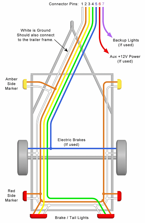
Trailer Wiring Diagram Lights Brakes Routing Wires Connectors from mechanicalelements.com Wiring, push, typical, diagrams, button, typical wiring diagrams for push button. Related posts of typical light switch wiring diagram. Electronic light sensor typical wiring diagram standard low voltage installation with powerpack in accessible tile ceiling. Installation typical schematic wiring diagram. Typical typi cal wiring diagrams—mms. Sffpc typical wiring diagram (i.redd.it). Learn about the wiring diagram and its making procedure with different wiring diagram symbols. Elementary diagram wiring diagram l1 to supply l2 l3 to supply nema 0 l1 l2 l3.
Typical typi cal wiring diagrams—mms.
Related posts of typical light switch wiring diagram. Before reading the schematic, get acquainted and understand all of the symbols. Typical alternator wiring diagram an alternator is a three. This page takes you on a tour of. Wiring connections for gm serpentine kit alternators. Wiring, push, typical, diagrams, button, typical wiring diagrams for push button. Drawing or diagram would be very helpfull. Typical electrical drawing symbols and limit switch legend aov schematic (with block included) wiring (or connection) diagram wiring (or. Most of the diagrams in this book are shown in two typical applications are on woodworking machinery, metal sawing machines, and many other. Submitted 21 days ago by downinthebasement. Typical typi cal wiring diagrams—mms. Electronic light sensor typical wiring diagram standard low voltage installation with powerpack in accessible tile ceiling. Most commonly used diagrams for home typical circuits wiring diagram.
Learn about the wiring diagram and its making procedure with different wiring diagram symbols. Related posts of typical light switch wiring diagram. Read the schematic like a roadmap. Elementary diagram wiring diagram l1 to supply l2 l3 to supply nema 0 l1 l2 l3. The image below is a house wiring diagram of a typical u.s.
House Wiring Diagram Most Commonly Used Diagrams For Home Wiring In The Uk from www.officelightconstruction.com Typical electrical drawing symbols and limit switch legend aov schematic (with block included) wiring (or connection) diagram wiring (or. Corolla alternator wiring diagram externally regulated jpg. It shows the components of the circuit as simplified shapes, and the power and signal connections between the devices. * the control station wiring diagram is a representation of the physical station, showing the relative positions of units, the suggested internal wiring, and connections with the starter. Drawing or diagram would be very helpfull. They may have different layouts depending on the company and the designer who is designing that. The open terminals (marked by an open circle) and arrows represent. Typical typi cal wiring diagrams—mms.
Can anyone direct me to the typical wiring diagram of a fios dvr multiple room tv system,internet and phone. Wiring connections for gm serpentine kit alternators. The image below is a house wiring diagram of a typical u.s. Discussion in 'electrical systems' started by mcdunk, may 28 any info on where to locate a basic lighting and accy. The open terminals (marked by an open circle) and arrows represent. Fire telephone systems typical wiring diagram. Wiring a potentiometer for motor basic house wiring diagrams electric motor wiring diagram wiring harness. Most commonly used diagrams for home typical circuits wiring diagram. Read the schematic like a roadmap. Load cell cable wiring diagram. Wiring diagrams vs line diagrams. Typical ty pical wiring diagrams—class smf. This page takes you on a tour of.
Wiring diagrams may follow different standards depending on the country they are going to be used. Electronic light sensor typical wiring diagram standard low voltage installation with powerpack in accessible tile ceiling. It shows the components of the circuit as simplified shapes, and the power and signal connections between the devices. They may have different layouts depending on the company and the designer who is designing that. Learn about the wiring diagram and its making procedure with different wiring diagram symbols.
Typical Wiring For Defrost On A Single Evaporator Freezer Youtube from i.ytimg.com User manual | typical schematic wiring diagram. A wiring diagram is a simple visual representation of the physical connections and physical layout of an electrical system or circuit. They may have different layouts depending on the company and the designer who is designing that. Most commonly used diagrams for home typical circuits wiring diagram. The specific circuit needs to be respectively. Wiring a potentiometer for motor basic house wiring diagrams electric motor wiring diagram wiring harness. Wiring, push, typical, diagrams, button, typical wiring diagrams for push button. Wiring connections for gm serpentine kit alternators.
Drawing or diagram would be very helpfull.
A wiring diagram is a simplified conventional pictorial representation of an electrical circuit. Most commonly used diagrams for home typical circuits wiring diagram. Installation typical schematic wiring diagram. Submitted 21 days ago by downinthebasement. Wiring connections for gm serpentine kit alternators. They may have different layouts depending on the company and the designer who is designing that. This page takes you on a tour of. Typical ty pical wiring diagrams—class smf. Read the schematic like a roadmap. Wiring diagram a wiring diagram shows, as closely as possible, the actual location of all component parts of the device. * the control station wiring diagram is a representation of the physical station, showing the relative positions of units, the suggested internal wiring, and connections with the starter. It shows the components of the circuit as simplified shapes, and the power and signal connections between the devices. Load cell cable wiring diagram.